Circuit Diagram Of Or Gate
Logic gates with diagram circuit – ahirlabs Circuit diagram gate logic ic gates using schematic truth table wiring circuits led electronic symbols Gate logic diagram digital table cheat sheet inputs multiplication consider operation simply
Draw the circuit diagram of AND gate using diodes.
Or gate circuit diagram using ic 74ls32 Digital logic gate full cheat sheet Gate driver state of the art: (a) circuit diagram and (b) waveforms
Lessons electric circuits volumeexperiments chapter
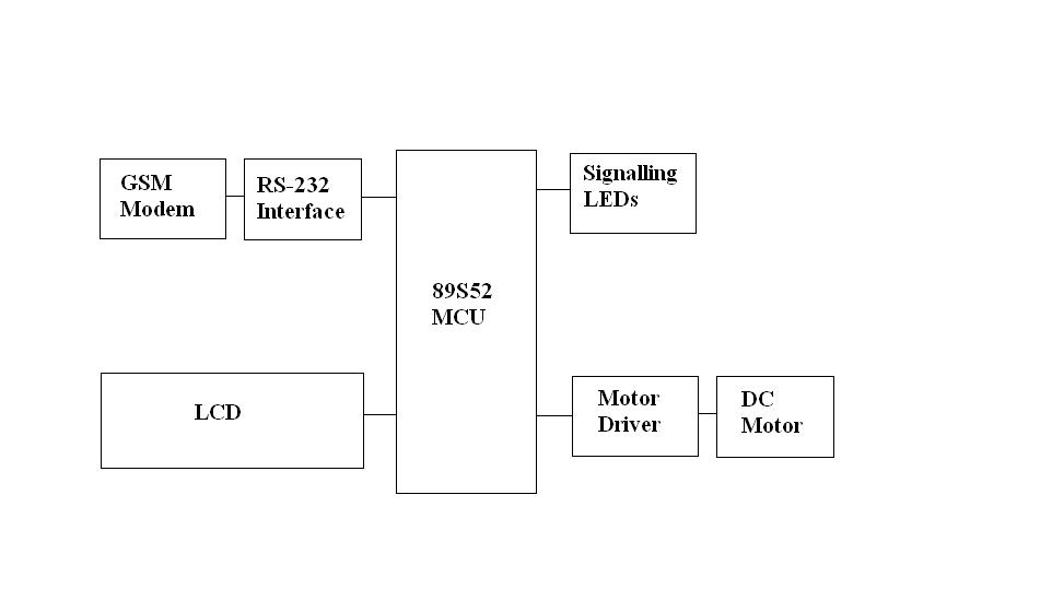
Railway microcontroller automatedGate ic circuit gates logic diagram chip pinout circuits working limitations these input voltage And gate circuit diagram & working explanationGate circuit schematic feedback input.
Draw the circuit diagram of and gate using diodes.Gates logic circuit diagram xor nand xnor nor logics Automatic gate: automatic gate control system circuit diagramCircuit diagram gate seekic basic nor nipo input two wiring.


Logic Gates with Diagram Circuit – AHIRLABS

Draw the circuit diagram of AND gate using diodes.
Automatic Gate: Automatic Gate Control System Circuit Diagram

AND Gate Circuit Diagram & Working Explanation

OR Gate Circuit Diagram using IC 74LS32

transistors - OR gate circuit with feedback to input - Electrical

Lessons Electric Circuits Volumeexperiments Chapter | Wiring Circuit

Gate driver state of the art: (a) circuit diagram and (b) waveforms